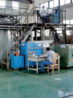
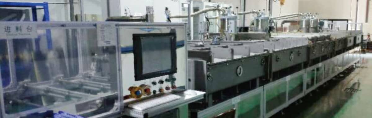
Advanced manufacturing equipments, automatic inspection equipments, high-tech R&D equipments
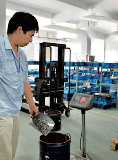
Compounding
Strip Casting
HD
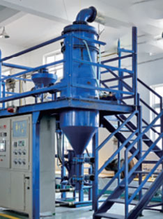
Jet Milling

Pressing
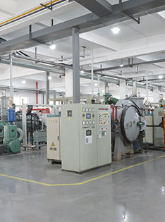
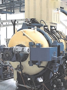
Sintering
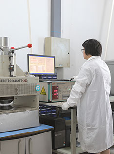
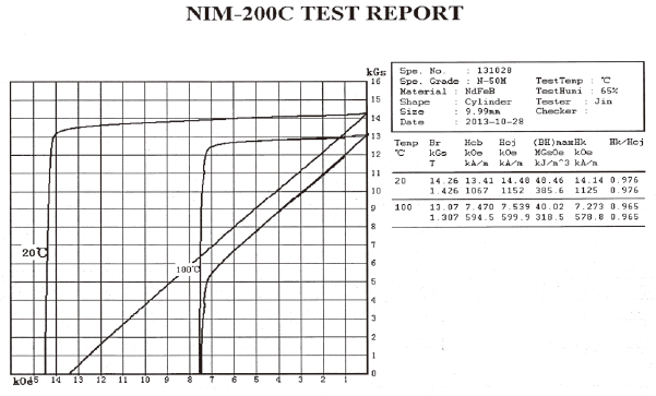
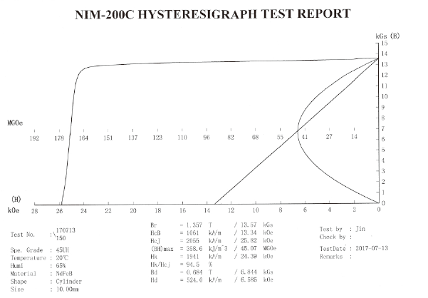
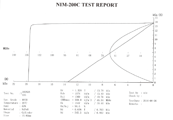
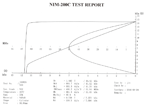
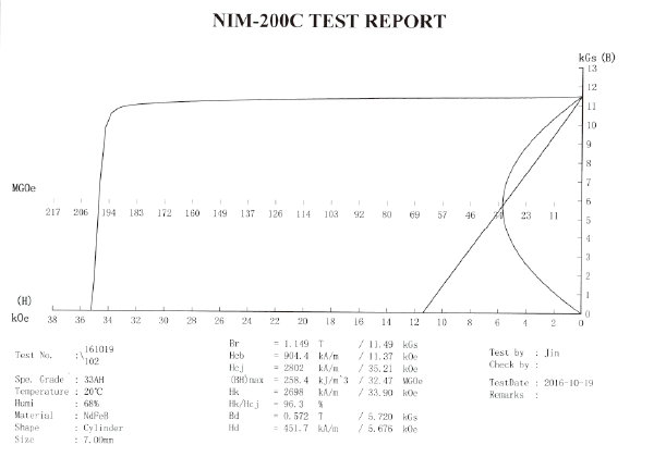
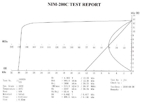
Magnetic Properties Testing
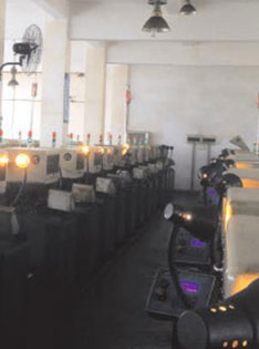
Machining

Inspection
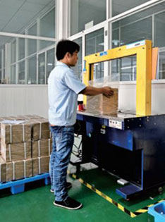
Packing

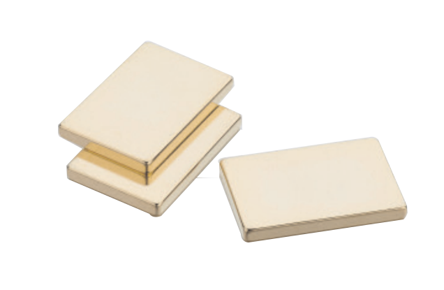
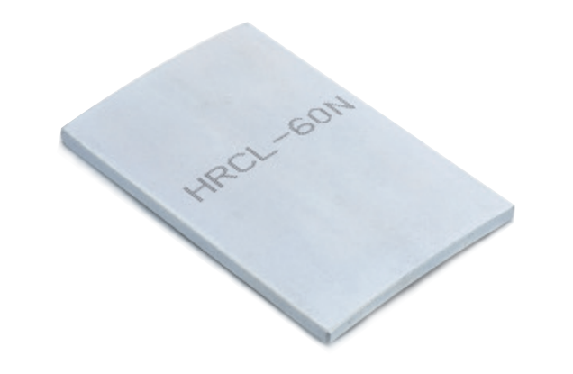

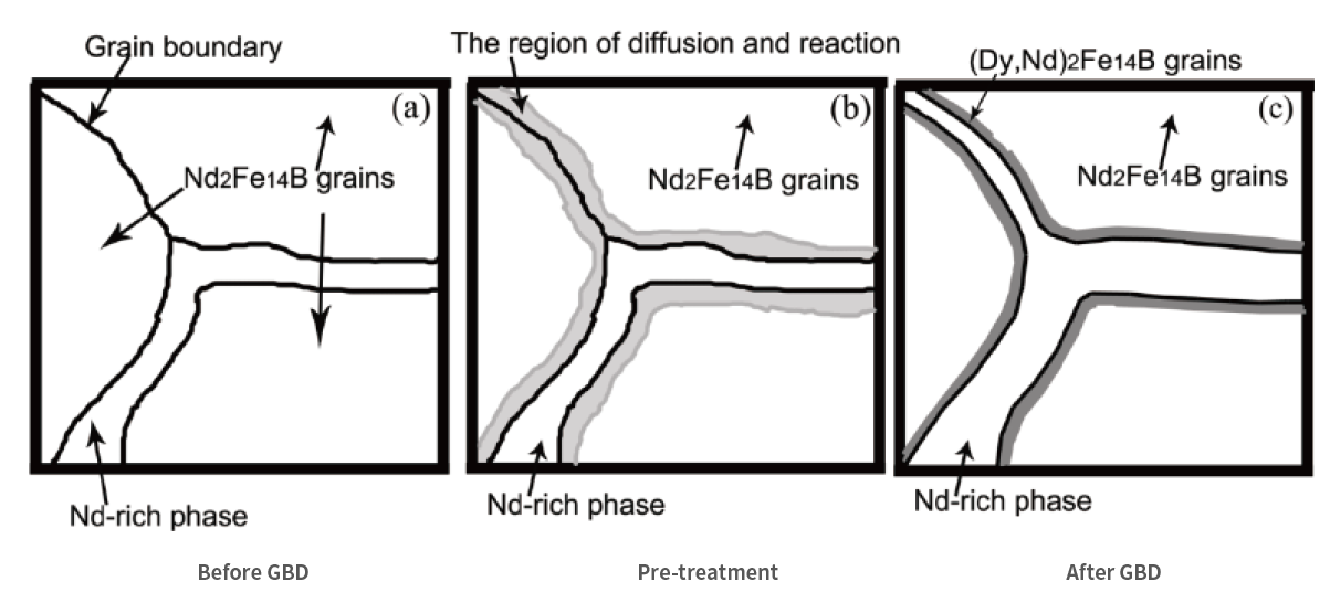
Grain boundary diffusion technology is to form a thin layer of Dy or Tb heavy rare earth on the surface of sintered NdFeB magnet sheet with thickness of 1-9mm by surface coating, magnetron sputtering, vacuum evaporation and electrophoretic deposition.After proper heat treatment and tempering treatment, the intrinsic coercivity of the magnet is greatly improved.It can reduce the use of heavy rare earths material, thereby reduce manufacturing costs. It can also produce high- performance magnet that can't produced by normal processes.
Manual feeding / automatic feeding
Automatic weighing
Workpiece heating
Automatic spraying (A side)
Automatic weighing
On line automatic turning material
Automatic heating
Workpiece heating
Automatic spraying (B side)
Automatic weighing
Unloading / automatic material receiving
Vacuum sintering furnace
| Content of heavy rare earth in formula | Product thickness(mm) | Increase range of Hcj during grain boundary infiltration of Dy(kOe) | Increase range of Hcj during grain boundary infiltration of Tb(kOe) |
| 0 | <4 | 4~5 | 7~8 |
| 0 | 4~8 | 3~4 | 6~7 |
| >2% | <4 | 3~4 | 6~7 |
| >2% | 4~8 | 2.5~3.5 | 5~6 |

Pls scan the code